-40%
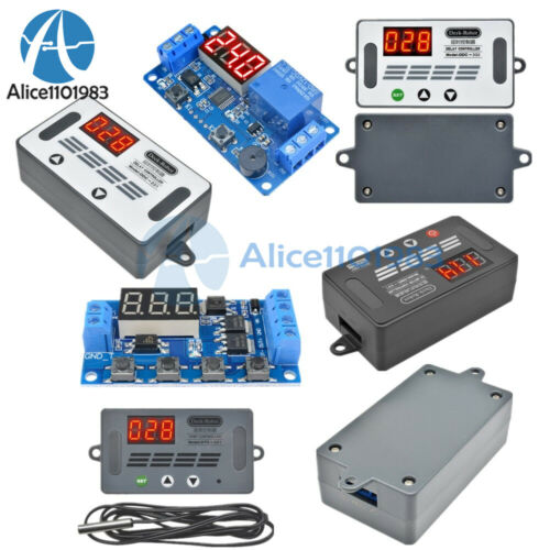
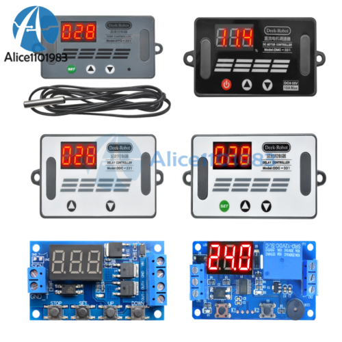
5V/12V 2/3/4 Button Timer Delay Relay Motor Speed Temperature Controller+Buzzer
$ 3.76
- Description
- Size Guide
Description
Visit storeItems for sale
About us
Product Details
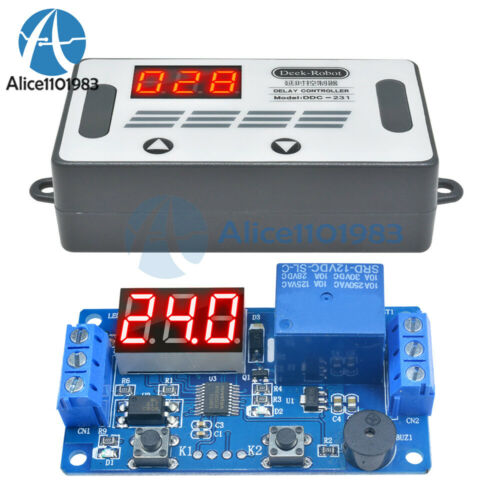
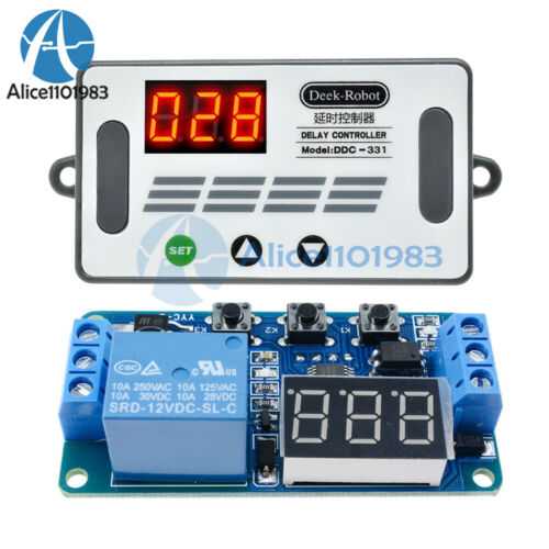
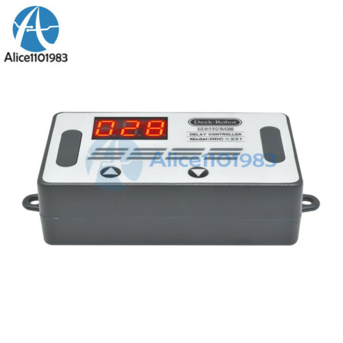
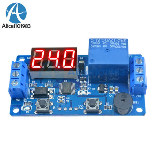
1.Digital Display Delay Controller:(DC 12V with Buzzer 2 Button
)
Product parameters
Working voltage: DC12V (normal working voltage DC10V-16V)
Signal source: DC4V~20V (usual power supply positive trigger, button, PNP sensor, PLC signal, etc.)
Output capability: It can control devices within 30v5A or within 220v5A
Quiescent current:
20mA, working current: 50mA
Service life: more than 100,000 times;
Working temperature: -40~85 °C;
Net weight: about 26g
Size: 64.2mm*34.8mm*18.5mm
Features
Voltage input anti-reverse circuit, worry-free wiring. Signal input optocoupler isolation, strong anti-interference ability. Set the parameter to power off permanent memory. Powerful flash MCU online programming function, according to user needs can contact the manufacturer to customize the required functions.
Function introduction
When the power is turned on, the trigger signal is received, the countdown starts, and the relay works. When the timer ends, the relay stops working, the time returns to the setting, and the next trigger signal is waited.
Instructions
1).Press K1 to enter the time setting, the hundred digit digital tube starts to flash; press K2 at this time, the hundred digits change; press K1 again, the ten digital tube starts to flash; press K2 at this time, the ten digits change; press again After K1, the digital tube starts to flash. At this time, press K2, the digit of the digit changes; press K1 again to exit the setting, and the digital tube no longer flashes.
2).When the digital tube is normally displayed, press K2, the decimal point is shifted, the decimal point is 0 to 999 seconds in ones digit, the decimal point is 0 to 99.9 seconds in ten digits, and the decimal point is 0 to 999 minutes; the time is set.
2.Digital Display Delay Controller:(DC 12V 3 Button)
Product parameters
Working voltage: DC12V (normal working voltage DC10V-16V)
Source: DC4V~20V (usual power supply positive trigger, button, PNP sensor, PLC signal, etc.)
Output capability: It can control devices within 30v5A or within 220v5A
Quiescent current: 20mA, working current: 50mA
Service life: more than 100,000 times;
Working temperature: -40~85 °C;
Net weight: about 26g
Size: 64.2mm*34.8mm*18.5mm
Features
Voltage input anti-reverse circuit, worry-free wiring. Signal input optocoupler isolation, strong anti-interference ability. Set the parameter to power off permanent memory. Powerful flash MCU online programming function, according to user needs can contact the manufacturer to customize the required functions.
Wiring diagram
Function introduction
P-1: The signal triggers the relay to pull in. When the time is up, the relay is disconnected during the delay.
A: Invalid trigger again B: Re-trigger re-clocking C: Trigger relay reset again to stop timing
P-2: The signal trigger start timing time T1, the time is up to the relay pull-in time T2 is disconnected (reset)
A: Invalid trigger again B: Re-trigger re-clocking C: Start delay without triggering power-on
P-3: Cycling: Turn on T1, disconnect T2, infinite loop. For T1 and T2, the time is adjustable; if a parameter is turned ON or OFF, it can be turned on or the power is turned on.
A: The relay is turned on immediately after power-on. B: The relay is turned off and then turned on after power-on.
P-4: There is signal, the relay is closed, the suction is kept, the signal disappears, the timing starts, the time is up, the relay is disconnected, during the delay, the signal is given again, the delay is cancelled, the relay is kept, the signal disappears, and the time is re-timed.
Notes
The relay output is a passive contact that has no live output and controls the on/off of a line.
3.Digital Display Delay Controller:
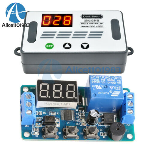
(DC 12V with Buzzer 3 Button)
Product parameters
Working voltage: DC12V (normal working voltage DC10V-16V)
Source: DC4V~20V (usual power supply positive trigger, button, PNP sensor, PLC signal, etc.)
Output capability: It can control devices within 30v5A or within 220v5A
Quiescent current: 20mA, working current: 50mA
Service life: more than 100,000 times;
Working temperature: -40~85 °C;
Net weight: about 26g
Size: 64.2mm*34.8mm*18.5mm
Features
Power input flash-coupled, strong-interference ability. Power of flash MCU online programming function, according to user needs can contact the manufacturer to customize the Required functions.
Function introduction
P-1: The trigger signal is received, the relay is turned on, the timer expires, and the relay is turned off.
A1: Invalid again during delayed trigger
A2: Trigger again during retiming delay
A3: During the delay trigger, the trigger signal is received again to terminate the current delay.
P-2: Receive trigger signal, X start time, relay off, Y start time, relay open
P-3: Cycle switching mode
A1: After the power relay is turned on, the timing is turned off and the loop is infinite.
A2: After the power relay is turned off, the timing ends and the loop is infinite.
Notes:
The relay output is a passive contact that has no live output and controls the on/off of a line.
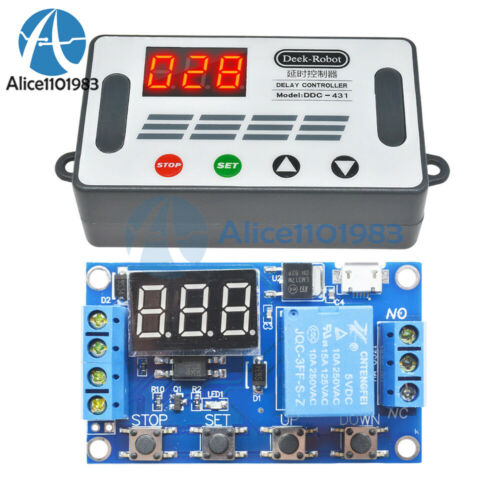
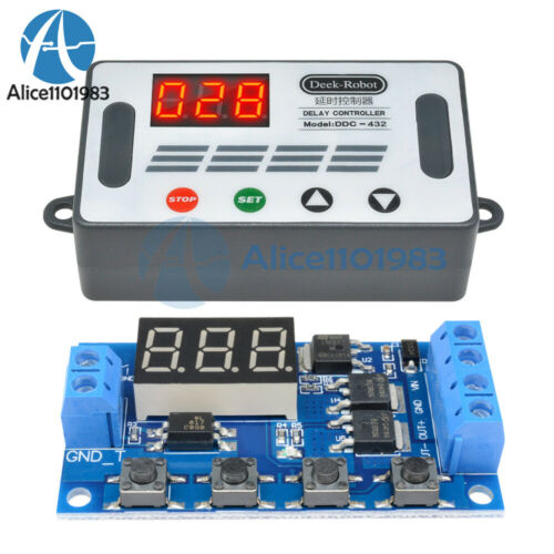
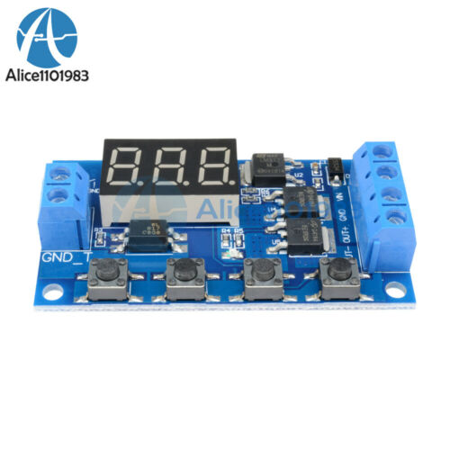
4.Dual MOS delay control board: (DC 5-30V 4 Button)
Description:
Dual MOS parallel active output, lower internal resistance, larger current, strong power interface, clear and simple, powerful, one-button emergency stop function (STOP button), with reverse connection protection, reverse connection, no burning, power-off memory. Increase Sleep mode, after enabling, no operation within 5 minutes, automatically turn off the display, wake up any button! You can set different OP, CL, LOP parameters, these parameters are independent of each other, save the setting parameters automatically power-down save and other functions, Almost all the needs!
Product manual
Working voltage: DC5V-DC30V (wide voltage anti-connection protection)
Trigger signal source: high-level trigger DC 3.0V—24V signal ground and system ground to improve the system's anti-interference ability can also short-circuit the ground
Output capacity: DC DC 5V--36V, continuous current 15A at normal temperature, power 400W! Under the condition of auxiliary heat dissipation, the maximum current can reach 30A
Product size: 64mm*35mm*19.3mm
Mounting hole: diameter 3mm
Working temperature: -40 ° C ~ 85 ° C
Operating mode
P1 mode: After the signal is triggered, the MOS transistor turns on the OP time and then turns off; in the OP time, the following operation
P1.1: The signal is triggered again.
P1.2: Signal triggers re-timed again
P1.3: The signal triggers reset again, the MOS tube is disconnected, and the timing is stopped.
P-2: Give the trigger signal, after the MOS transistor is disconnected from the CL time, the MOS transistor turns on the OP time. After the timing is completed, the MOS transistor is disconnected.
P3.1: Give the trigger signal, after the MOS transistor turns on the OP time, the MOS tube turns off the CL time, then loops the above action, the signal is given again in the loop, the MOS tube is disconnected, the timing is stopped; the number of cycles (LOP) can be set.
P3.2: No need to trigger signal after power-on, MOS tube turns on OP time, MOS tube disconnects CL time, loops the above action; loop number (LOP) can be set
P-4: Signal hold function If there is a trigger signal, the timing is cleared, the MOS transistor remains on; when the signal disappears, the MOS transistor is disconnected after timing the OP; during the timing, there is a signal and the timing is cleared.
Relay enable mode
ON : MOS tube is allowed to conduct during OP conduction time
OFF : MOS tube is disabled, always off
Short press the STOP button on the main interface to switch between ON and OFF. The current state will flash, then return to the main interface. This function is the emergency stop function. One button is used to open and close the MOS tube.
Sleep mode (long press the stop button to view the current mode)
C-P sleep mode: within five minutes, without any operation, the digital tube automatically turns off the display, the program runs normally.
O-d normal mode: the digital tube is always on display
Press and hold the STOP button for 2 seconds and then release to switch the C-P and O-d states. The current state will flash and then return to the main interface.
Timing range
How to choose the timing range
1).After setting the parameter value in the mode selection interface, press the STOP button to select the timing range.
XXX. Decimal point is in one place, timing range: 1 second to 999 seconds
XX.X decimal point in ten, timing range: 0.1 seconds to 99.9 seconds
X.X.X. The decimal point is fully illuminated, the timing range is from 1 minute to 999 minutes.
2).For example, if you want to set the OP to 3.2 seconds, move the decimal point to ten digits, and the digital tube displays 03.2.
Parameter description: OP on time, CL off time, LOP cycle number 1-999 times, "---" stands for infinite loop.
These parameters are independent of each other, but each mode shares these parameters. For example, when the on-time OP is set to 5 seconds in P1.1, the user wants to switch to the P1.2 mode, then when entering the P1.2 setting corresponding parameters, the OP also It will be 5 seconds.
Displaying 000 on the main interface and pressing the SET button will display OPL, LOP and corresponding time XXX
If only OP in the mode, such as mode P1.1, P1.2, P1.3 time, then short press SET button will only display OP and corresponding time.
If the mode has OP, CL, LOP such as mode P3.1, P3.2 short press SET button will display OP and corresponding time, CL and corresponding time, LOP and corresponding times.
After setting the mode, it is very convenient to easily check the parameters set in the current mode by pressing the SET button on the main interface.
How to set parameters
1) First determine the working mode of the MOS tube
According to the working mode of the MOS tube, in the main interface (when the module is powered on, it will flash the current working mode (default P1.1 mode), then enter the main interface "press and hold the SET button for 2 seconds and then release" to enter the mode. Select the interface, press the UP, DOWN button to select the mode to be set P1.1~P-4
2) After selecting the mode to be set (for example, P3.2), press the SET button to set the corresponding parameter. At this time, the parameter to be set will flash OP ON time, CL OFF time, LOP cycle number “---” Represents an infinite loop, adjusts the parameter value through UP and DOWN, supports long press (rapid increase or decrease) and short press (increase or decrease 1 unit); after setting the parameter value, select the decimal point position by short pressing the STOP button. , select the timing range (corresponding time 0.1 seconds ~ 999 minutes); short press the SET button to set the next parameter of the current mode, the process is the same as above.
3) After setting the parameters of the selected mode, press and hold the SET button for 2 seconds to release, the currently set mode will flash, then return to the main interface and set the parameters successfully.
4) Main interface: “000” (no decimal point) is displayed when the MOS tube is not working, and the MOS tube has a decimal point in the working state.
5) Mode selection interface: long press SET button to enter, after setting is completed, long press SET button to exit, return to the main interface
Note:
The module is an active live output, and the voltage at the output (load) is equal to the input voltage DC
5.USD Digital Display Delay Controller: ( DC12V 4 Button )
Description:
This relay delay control board has a powerful and clear interface, powerful function, one-button emergency stop function (STOP button), with reverse connection protection, reverse connection without burning, power-off memory. Increased sleep mode, after enabling, No operation within 5 minutes, automatically turn off the display, wake up any button! You can set different OP, CL, LOP parameters, these parameters are independent of each other, save the setting parameters automatically power-down save and other functions, almost meet all needs!
Product manual:
Working voltage: DC6V-DC30V (wide voltage anti-connection protection)
Trigger signal source: high-level trigger DC 3.0V—24V signal ground and system ground to improve the system's anti-interference ability can also short-circuit the ground
Output capacity: controllable DC 30V/10A or AC 250V/10A equipment
Product size: 64mm*35mm*19.3mm
Mounting hole: diameter 3mm
Working temperature: -40 ° C ~ 85 ° C
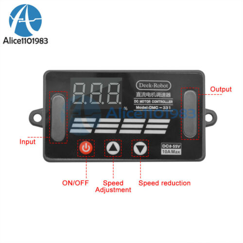
6.DC Motor Speed Controller :(DC 8-55V Motor Speed Controller )
Description:
This product brings together a wide range of modern motor speed control, with the advantages of small size, simple operation, high current resistance and reverse connection. Suitable for most users in various environments with various speeds, support acceleration and deceleration functions can be set through the menu, with set parameters power off permanent memory function
Product manual:
Voltage: DC8V-55V (wide voltage anti-back protection)
Speed range: long press / short press to adjust the degree, 0% -100% speed
Drive current: up to 10A, (recommended output series 12A fuse)
Standby current: <17mA
Mounting hole: diameter 3mm
Product size: 64mm*35mm*19mm (length * width * height)
Working temperature: -20 ° C ~ 70 ° C
Instructions:
1. Click/long press the “speed increase” button to increase the motor speed to 100%.
2. Click/long press the “speed down” button to increase the motor speed to a minimum of 0%.
3. Press and hold the “Power On/Off” button for one second, the controller will be turned on or off (the power is turned off by default, and the memory function is activated after booting)
Precautions:
1. The digital tube flashes at the moment of power-on (normal phenomenon, no need to worry)
2, close to the limit drive current working conditions, it is recommended to take the output end of the fuse
3. The DC motor speed controller cannot be installed in places where there is dripping water and children can reach it.
4. After wiring, check if the line is correct and then energize, so as to avoid accidentally burning the temperature controller and load device.
Wiring:
“M+” and “M-” are respectively connected to the positive and negative terminals of the output, M+ is positive and M- is negative.
“VIN” and “GND” are respectively connected to the positive and negative terminals of the input terminal, Vin is positive and GND is negative (input power supply voltage is DC8V-55V)
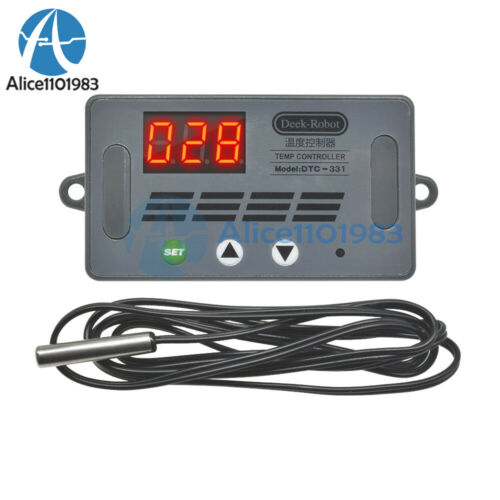
7.Temperature Controller:(DC 12V Temperrature Controller)
Product Parameters:
Control range: -50~110°C
Resolution: -9.9~99.9, 0.1°C, other temperature range, 1°C
Temperature measurement accuracy: 0.1 °C
Control accuracy: 0.1 ° C
Hysteresis accuracy: 0.1 ° C
Refresh rate: 0.5S
High temperature alarm: 0-110 °C
Measurement input: NTC (10K0.5%) waterproof sensor
Output: One way 10A relay
Environmental requirements: Temperature -10~60°C Humidity 20%-85%
Size: 48*40mm
Power consumption of the whole machine: quiescent current: ≤35MA, Pull-in current: ≤65MA
Setting Parameter Method:
Once the power supply and load are connected, the control can be powered. After power-on, the digital tube displays the current real-time temperature. Press the SET button briefly, the digital tube displays the temperature flashing, press the + - button to adjust the set temperature; after the adjustment is completed, press the SET button to save the set temperature and return. At this time, the controller automatically Execute the relay on and off; press and hold the SET button for 5 seconds to enter the menu parameter setting, short press the + - button to switch P0...P6, short press the SET button to enter the menu.
The thermostat output is a 10A relay to meet a variety of high power loads, please ensure that the line is correct.
Indicator light, digital tube status description:
Indicator light: Off means the relay is off, steady light means the relay is closed
Digital tube: Display LLL for sensor open circuit: Display HHH is out of measurement range. The thermostat will forcibly open the relay.
Parameter Function Description:
Menu identifier
Menu function
Predetermined area
Factory setting
P0
Refrigeration C / Heating H
C/H
C
P1
Backlash
0.1-15
2.0
P2
Maximum set temperature
-50~110℃
110
P3
Minimum set temperature
-50~110℃
-50
P4
Temperature correction
-7.0~7.0℃
0.0
P5
Press delay
0-10 minutes
0
P6
High temperature alarm
ON/OFF
OFF
Package Included:
1PC*DC 12V 2/3/4 Button Time Delay Relay Motor Speed Temperrature Controller+Buzzer
(According to your choice)
Payment Method
Shipping Policy
Returns & Refund Policy
Feedback
Payment Method
EBAY Managed Payment.
But we only
Accept
your
Ebay Address
, please Make sure it's 100% right.
Payment must be received in 5 business days of auction closing.
Please leave note for your special request (e.g. Colors or Size) in PayPal when you pay the order.
Any special request cannot be accepted after 24 hours of payment, because most of orders will be processed instantly and same day dispatched.
Shipping Policy
1. We only ship to the confirmed address provided by eBay. please make sure your ebay address is 100% matches the address you would like us to ship to. If not, please let us know before we sent you the package, or we will not be responsible for any loss. hope you could understand.
2. Orders will be processed instantly and dispatched within 1-3 business days except hoilday, so we do NOT accept any email/message note after you place orders.
3. All package need to wait 30 days,Please take care it.Less than 30 days,we can't take a refund.
Returns & Refund Policy
All package need to
wait 30 days
(US only n
eed 7-10 days)
,
Please take care it.Less than 30 days,we can't take a refund
.
If the item is defect when you receive it or you are not satisfied with it, please return it within 14 days for a replacement or money back. But the items must be back in factory condition. Please keep in touch with us and double check the return address before you return it.
If is item is defective in 12 months, you can return it to us. We will send you a new replacement after receiving the defective item.
Feedback
We maintain high standards of excellence and strive for 100% customer satisfaction! Feedback is very important to us. We request that you keep in touch with us immediately BEFORE you give us neutral or negative feedback, so that we can satisfactorily address your concerns.
